
An evaluation of the different methods proposed to tackle the task of building the Machine Writing fonts.
INTRO
With the idea settled, it was time to get to work. The chosen language for developing was Java—it’s the language that I have the most experience with, and I knew that it would be able to provide everything that I need for this project.
The basic class structure for the letter system was quite simple to set up. It goes as follows:
The Writer class—the one that runs the show—has one or more Alphabets. Each Alphabet then has its set of Letters. Each Letter then has a reference to the file that stores the vertex information for that Letter.
With the structure out of the way, I was pretty quickly faced with the challenge of actually defining the letters.
LETTER DEFINITION METHODS
I assessed the situation and boiled it down to four distinct methods for defining the letters. Each has its positives and its negatives, and each would work in the end, but that’s about where the similarities end.
METHOD 1: Manual Input
Writing GCode isn’t hard. There aren’t many commands, and it has a no-BS, straightforward syntax that makes it easy for humans to decipher. With this in mind, the first Letter Definition Method (henceforth LDM) was simply hardcoding the letters into text files—writing the GCode by hand.
The first test letter was defined this way, and it worked fine. It got the job done. The process has minimal hassle, with almost no time lost in setup. That’s about where the positives of this method end.
Hardcoding sucks. I’d had the unfortunate experience of doing it a few times in the past (my experience manually programming hex for each byte of a 32kb EEPROM in high school immediately comes to mind), and by the end of a coding session it can be difficult to reset your brain back to human mode.
In addition to this, once the data is entered, it isn’t easily editable or accessible. If I wanted to vary the characteristics (height, width, feedrate, etc.) of characters after the fact, it would require a pretty complicated parsing and rewriting algorithm. It’s essentially a bitmap image: once it’s there it’s there, and there’s no easy way to edit it.
METHOD 2: Array Definition
This LDM involves manually defining the array of points that string together to make each letter.
In terms of after-definition utility, this method clearly outshines the first. Its nature as a vector set of points allows for easy manipulation and modification, a necessary quality if I wanted to give the user room to set size, shape, and spacing settings.
It’s no walk in the park to code, though. It would require mentally picturing each letter as a single connected path in 3-space, defining and entering in the points one by one. Along with taking forever and being an overall headache, it has a huge potential for error, and there would be real way of checking my work, short of writing out the letter with the machine and seeing what happens.
METHOD 3: Visual Definition
Simply Method 2, expanded. The idea behind this LDM is to enter in the letter segments visually, by building some sort of GUI where each possible letter vertex would be a button that you could click, clicking one after another until the whole letter has been defined.
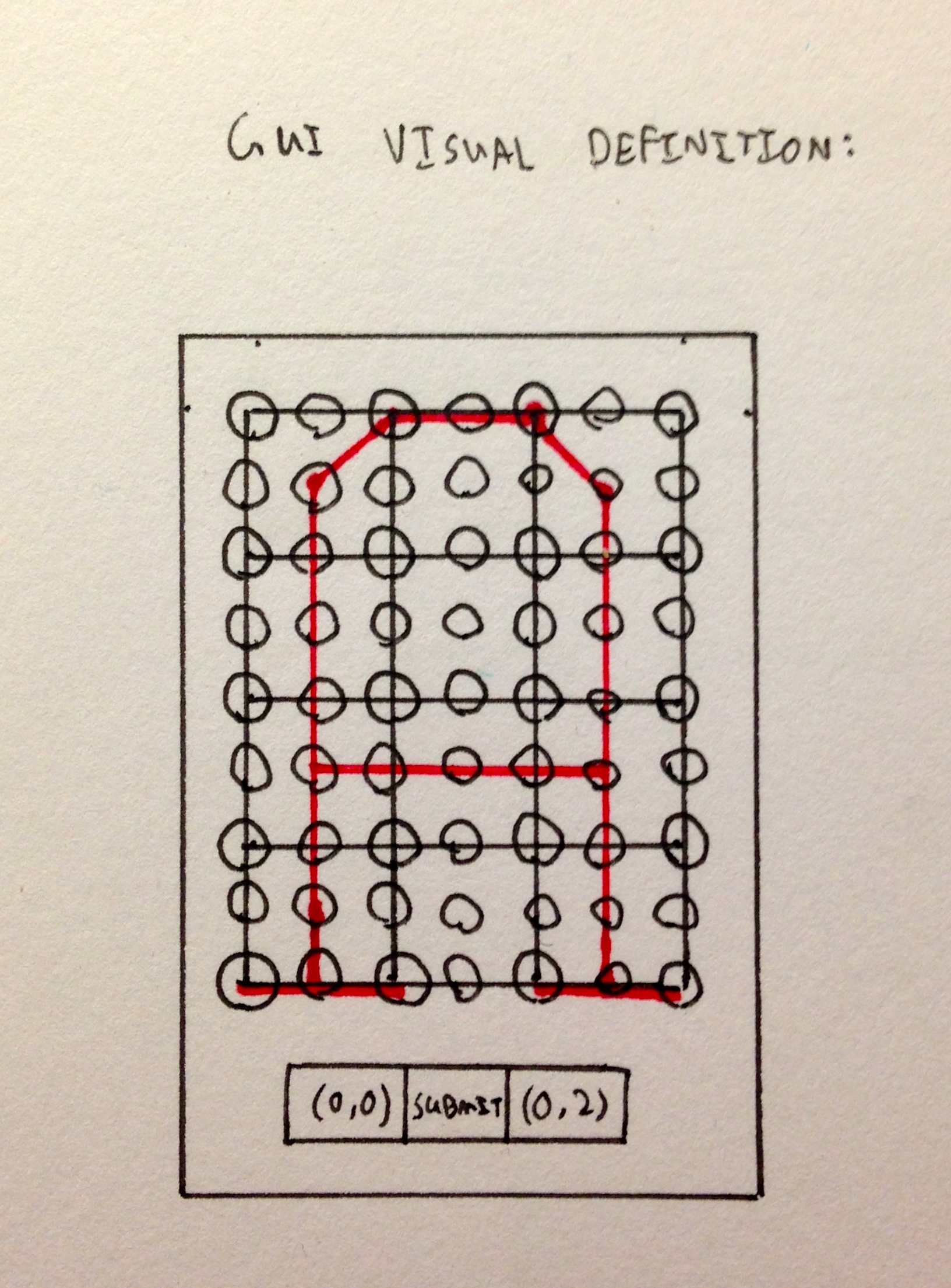
It would retain all of the functionality of the previous method, but would be much easier on the brain. Probably easy enough to get through a whole alphabet without losing too much sanity.
It’s extremely limited by nature, however. The letters would have to be pretty low resolution—every resolution increase would result in exponentially more buttons. A huge, disgusting 2D array of buttons. And then it would need more buttons. Not to mention each of these buttons needs its own listener. On top of all of this, the GUI would have a very short useful lifespan when compared to its development time.
METHOD 4: Vector Graphics & Existing Software
Every cut that I’d previously done with my machine started as a vector in Adobe Illustrator, and moved through Vectric Aspire to generate the toolpath. The method worked, and all in all the workflow was pretty smooth. Smooth enough to want to do it for 50+ characters? Probably not.
I already had my full alphabet drawn out in Illustrator. I did the full drafting for the font in the program, and thus had a finished set assembled and ready to go. It would have been as easy as saving each letter as an individual vector file, heading over to Aspire, and exporting a toolpath. Wait, that’s not easy at all.
This LDM would have been a tedious stream of saving, switching programs, importing, exporting, clicking, clacking.
Additionally, toolpaths exported from Aspire come with a ton of unnecessary baggage. Since it’s software made to generate legitimate toolpaths for cutting materials, GCode from it comes along with a whole host of spindle commands, feedrate restrictions, the works. It also can’t be easily scaled since it wouldn’t be in vector form.
It’s a professional piece of software made for machining. It wasn’t designed with this application in mind, and unsurprisingly it isn’t well suited for it.
Those were the four methods I could come up with when I started the pro/con weighing process. Do any of those methods sound good to you? They didn’t to me, either.
The act of listing out the characteristics of each LDM—what it’s good at, what it isn’t, what setup it required—helped me realize what I was really looking for. The hands-down best solution wasn’t one of the initial ideas, but it was sitting right in front of me the whole time.
METHOD 5: Blender 3D Path Definition
If you’ve read my previous BUILD post Playing Rock, Paper, Scissors with a Cheating Robot you’ve noticed that I like to use Blender 3D—a free, open source 3D graphics rendering engine—for informal models during the design planning process.
It does much, much more than just render pictures. Blender has a huge library of model exporting scripts, and has an inline Python scripting engine if you couldn’t already find what you were looking for.
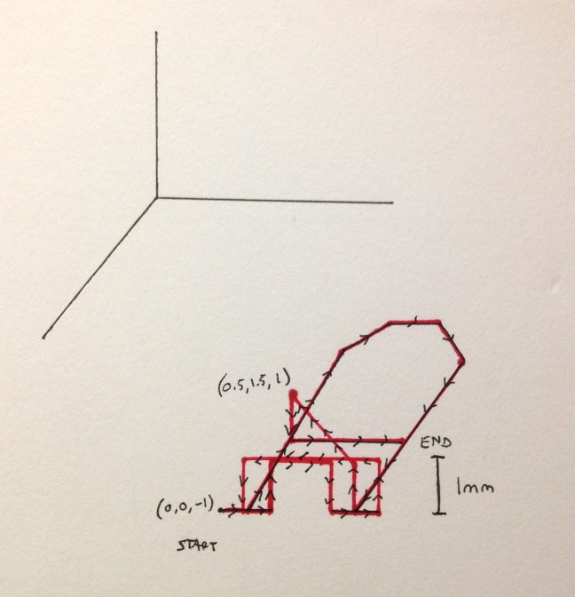
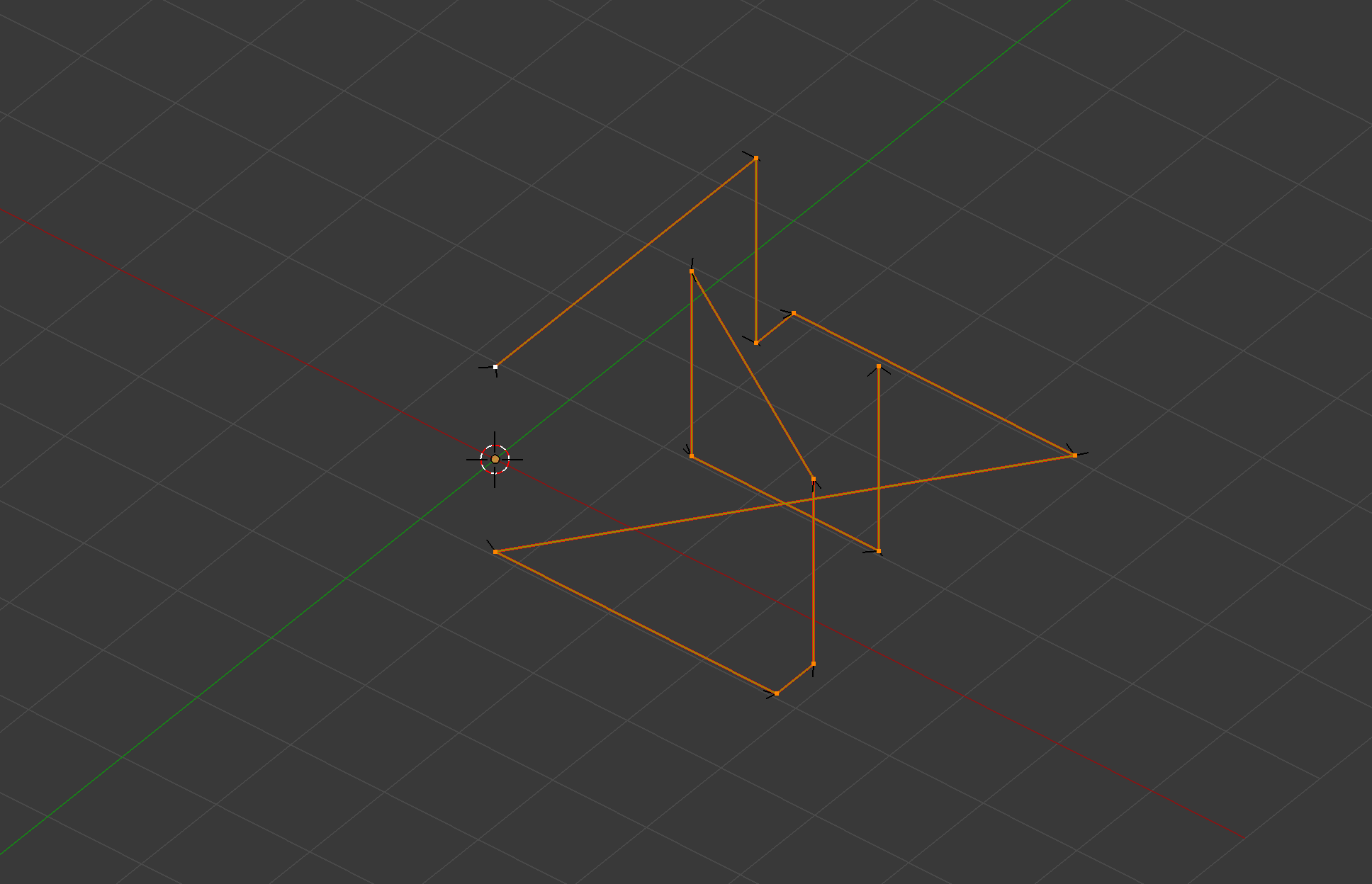
This is how it becomes an LDM. I hinted at it in the other methods, but the easiest way to define each letter would be to plot it out as one continuous line in 3-space. The X-Y plane would represent the drawing surface, and a negative Z value would correspond to the pen at drawing height, while a positive Z value would represent the pen at a moving height. This neatly handles the issue of getting the machine to pick up the pen between disjointed segments, of which most letters have at least one.
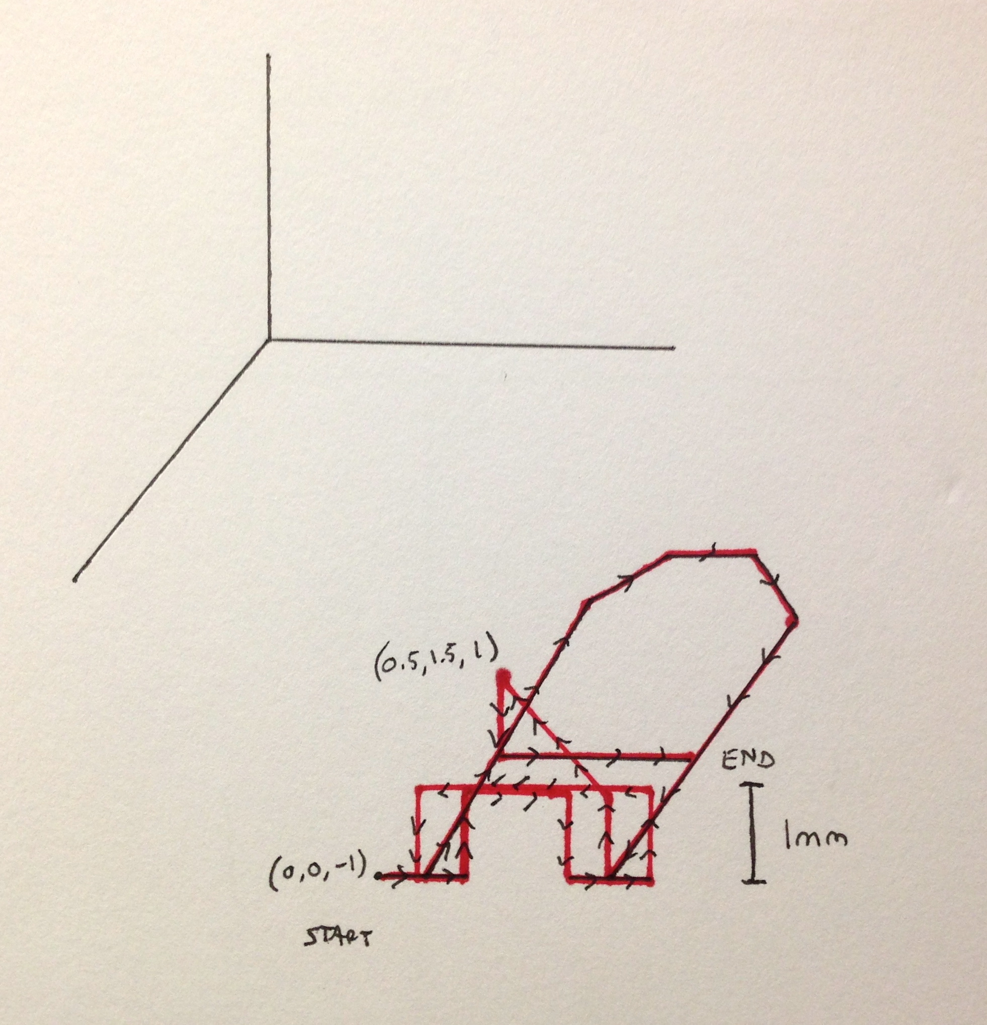
With letters plotted out in this fashion, the final step of definition was to use Blender’s built-in .OBJ export script, which exports your objects into a file format that stores vertex, face, and material information. Before looking into the exporters that ship with Blender, I had started to write my own Python exporting script specifically for this task. While doing research for this, I came across the .OBJ export file format (a stock Blender exporting script), and decided that it was good enough. It has the same functionality as the script I was planning on writing, and doesn’t require very difficult handling to extract the vertex values. The only problem that I encountered was that, for some reason or another, it exports vertices using a left-handed coordinate system: given X values correspond to real X values, given Y values correspond to Z values, and given Z values correspond to -Y values. A simple reshuffling of the order and sign of vertex values, and it was good to go.
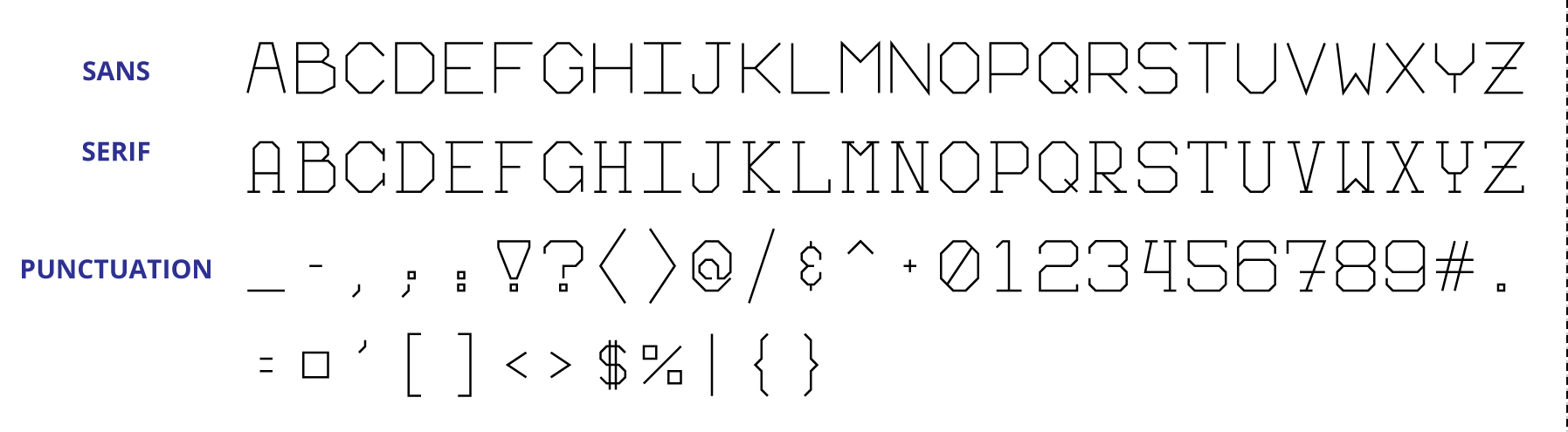
Blender’s fast, responsive, and intuitive user interface made plotting each letter’s line segments a breeze. Once I got the system set up and running, each character took roughly 45 seconds—that’s for the whole process: opening the base file, drawing the letter, saving, and running the .OBJ export script. Before I knew it, I was through the full Serif alphabet, and even had the will left to define another (multiple fonts were not part of the original plan).
TAKEAWAY
In the end, the solution wasn’t one of the four methods I had initially come up with. Instead, the wining LDM took the good aspects of each and combined them into a final setup, while leaving the negatives behind. Once again, Blender proved to be a fantastic tool: it’s essentially a 3D sketchpad that you can use in whatever way you wish, similar to what Illustrator is to the 2D world. Once you get over the initial learning curve, Blender becomes a tool that lets you think and create in three dimensions fluidly, with almost no limits on the number of different tasks you can use it for.
That being said, any of the above solutions would have worked. They all would have resulted in the machine writing letters exactly as I had defined them. However, that doesn’t mean any of the first four LDMs are good solutions.
It didn’t matter to me if I would have only had to enter in letters (whichever way) one time, taking no longer than a few hours for even the least efficient method. Doing it efficiently was a matter of principle to me. Why would I willingly waste my time doing mindless repetitive work when I could come up with a simpler and cleaner solution?
GH
