

A mechanical solution to a persistent problem: an exercise in lasercut component design.
INTRO
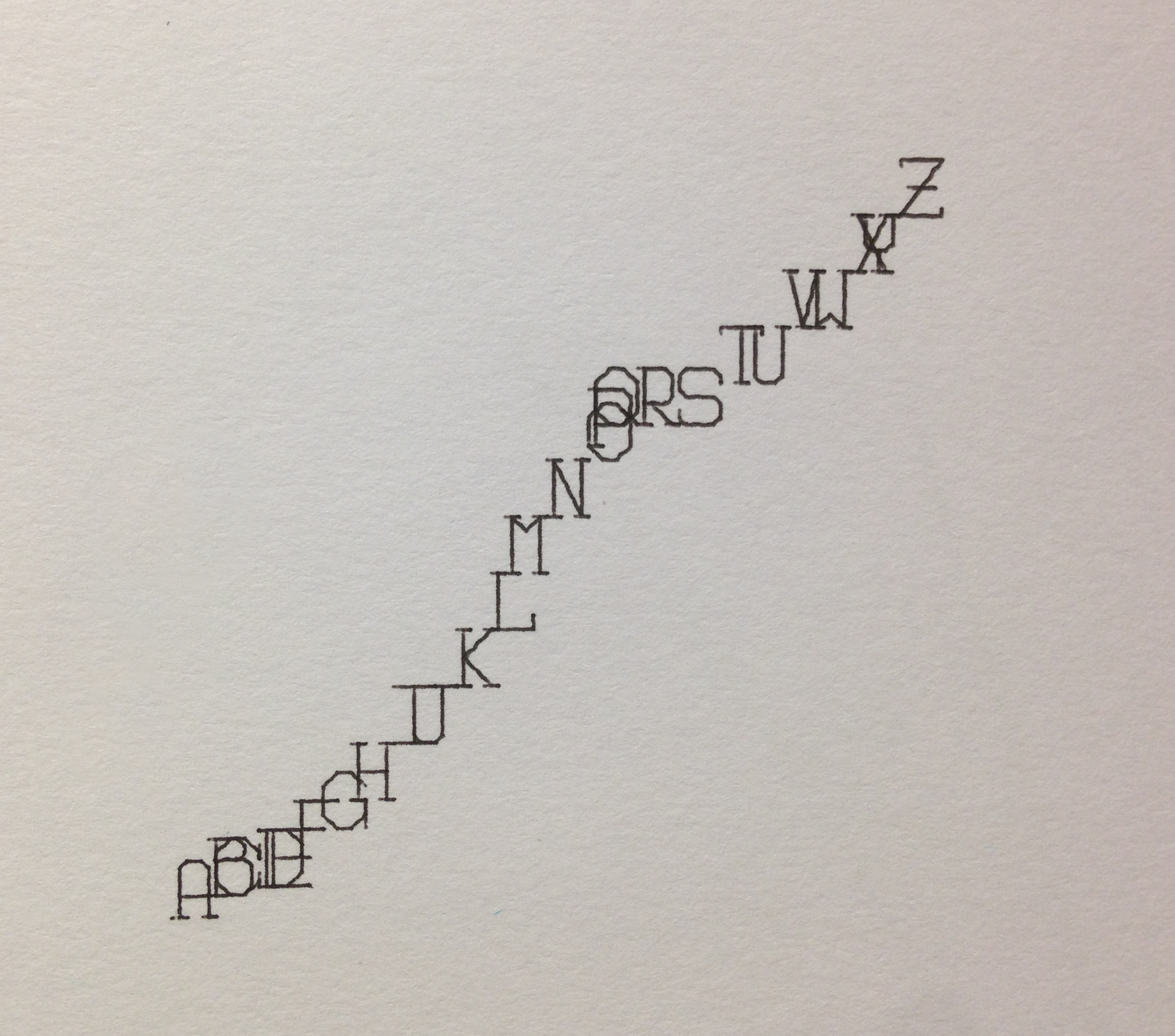
With the alphabet(s) fully defined, the Machine Writing project was off of the ground.
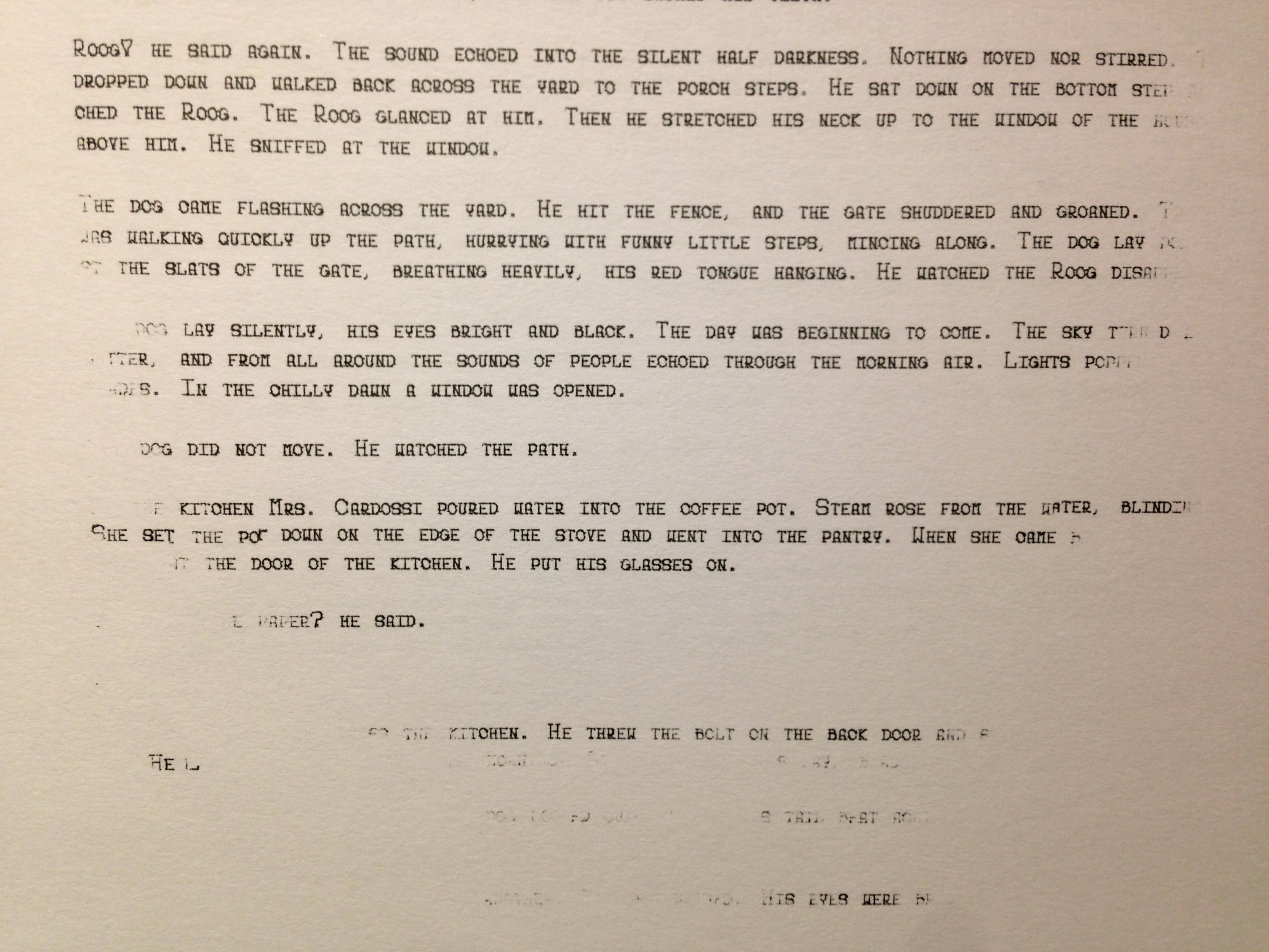
The first tests were exhilarating—seeing the machine actually do what I intended it to do immediately validated the hours on end spent staring at a computer screen. Never mind the fact that at this point it was still wildly bug-infested, it was writing words right in front of my eyes. Satisfying.
As I continued testing and squashing bugs one by one, I found that the most important factor in getting it to write smoothly was getting it perfectly leveled with the writing surface. This wasn’t impossible, but a small lapse in concentration when doing manual Z-Axis calibration and I ended up with a five-page deep hole in my test notebook. Repeat a few more times, and I knew that I had to do something about this problem.
PLANNING
It was clear that the most effective way to do dynamic toolhead leveling would be to implement a suspension system. Put a spring between the pen and the machine Z-Axis, and instead of forcing the pen tip through the writing surface, all a miscalculation or calibration error does is compress the spring. A system like this would give me a large sweet spot to calibrate to, and would allow the machine to write smoothly across a page whose height may vary by a millimeter or more from one corner to the opposite.
OK, I admit, the intro to this post may have been a little misleading. I didn’t just run into this Z-Axis leveling problem—I’ve been sitting on a 3D-print CAD model for exactly this application for months. I’ve wanted to be able to write or draw with my machine for almost as long as I’ve had it, and I knew that a spring-loaded pen suspension system would solve all of my Z-Axis issues.
That being said, I’ve been unable to find a single working 3D printer around town. The architecture/mechanical manufacturing research lab (LIPHE) wanted to charge $1.00 per GRAM for a standard PLA print (what?), the various student groups that offer services had month long backlogs (due to constantly “broken” machines), and individual students in the city with apartment-run printing services were flaky and unreliable. I mentioned it in my Machine Writing intro post, but the frustration around 3D printing on campus almost led me to convert my Shapeoko into a 3D printer. Sigh.
With 3D printing all but completely off of the table, I needed a different solution. I could have designed and cut parts out with my machine—after all, that is its intended use. But with my ShopVac out of commission for the foreseeable future and the spindle setup entirely disassembled, I decided that it would be more hassle than it was worth. Having used them many times before, I knew that the lasercutters on campus are reliable, inexpensive, and available 24/7. Lasercutting it was.
DESIGN
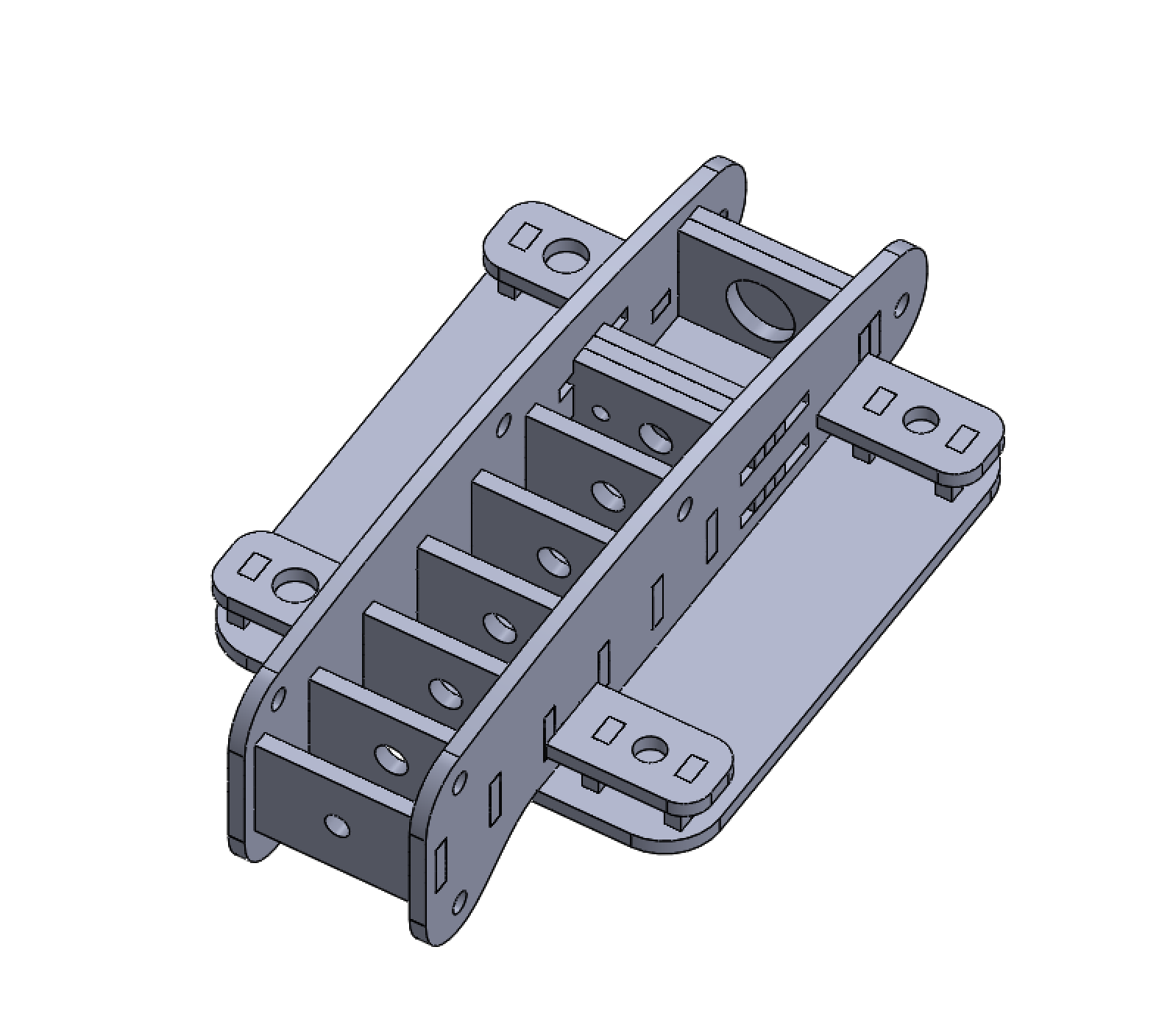
The lasercutter is a great tool. It’s fast and relatively hassle free. For most purposes the “toolhead” radius is negligibly small. All of these benefits come with a price: solely planar components.
In my experience, designing assemblies made up of purely planar parts is roughly 40% building the functionality and 60% making sure it won’t fall apart. You can always just glue the parts together (Krazy Glue and acrylic work very well together, and you can find even better acrylic epoxies online), but where’s the fun in that? I don’t know where I picked it up, but I have an ingrained aversion to the use of tape or glue. As such, this assembly is held together by an assortment of screws: four screws parallel to the face of the mounting plate, two to hold together the slider piece, and the four mounting screws already in place on the Shapeoko Z-Axis mounting plate.
The main design decision in this project was the method of holding the pen. There were two main options:
- Clamp the pen down to a v-brace or similar mechanism, and have entire pen/clamp able to slide (spring-load the entire pen fixture)
- Leave a hole or chamber exactly sized to a pen, and have only the pen slide
The first option has the clear benefit of being able to handle any type of writing utensil. With its one-size-fits-all design, if a certain pen wasn’t working, I could easily swap it out for one with a different size and shape. However, it would require a sturdy clamping mechanism, and a large spring to handle the whole assembly shifting up and down.
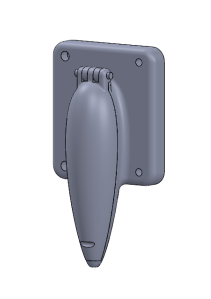
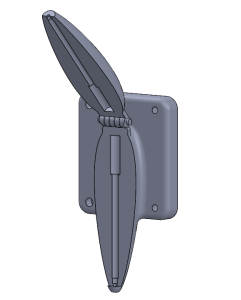
The second option does not have the versatility of the first. It would be designed to fit one predetermined pen cartridge, just like the 3D print model I had designed earlier. This is an obvious drawback. However, the fact that it’s built for one pen only allows it to handle that one pen well. The precisely sized “borehole” through the center of the part keeps the pen very steady in the XY-plane, allowing only up/down movement.
As I said earlier, the lasercutter’s “toolhead” is so small as to be negligible in most cases. This was not one of those cases. In my experience with 3mm acrylic cuts, the laser eliminates roughly a quarter of a millimeter total, half on each side of the cut line. In this scenario, 0.25mm+ of play in the XY-plane is enough to really mess up letter legibility. If I were to go with the first design, I would have had a very tough time getting the slider to move smoothly in the Z direction without allowing any X-Y play. Thus, the second solution was chosen.
An hour or so of cadding and another hour the following day to cut, and I had myself a penholder. As I had suspected, the slider part was not very sturdy in the X-Y plane, so I was relieved to have selected the less versatile but more reliable design solution.
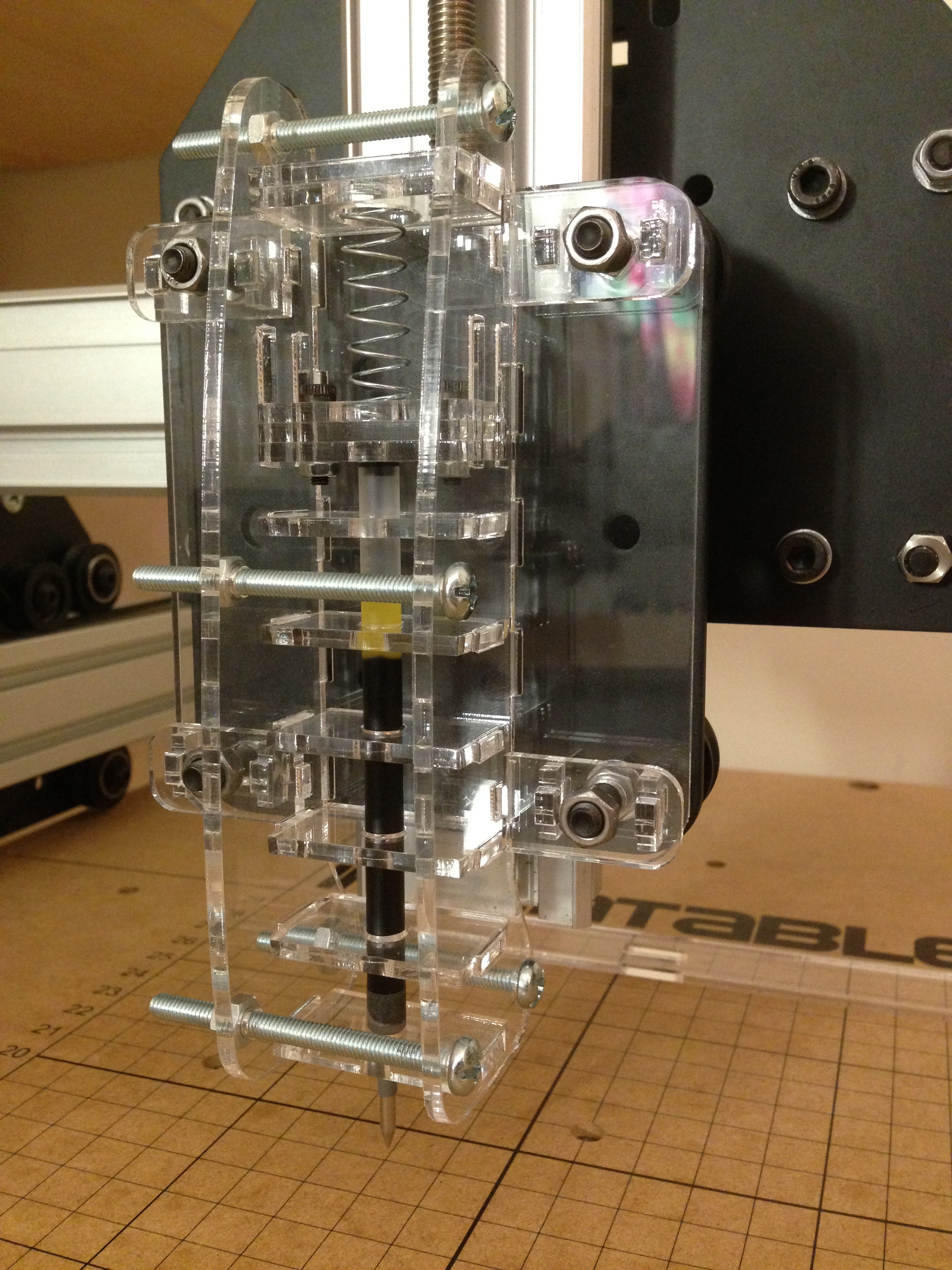
Functionally, it works like a charm. The pen fits perfectly, moves smoothly, and compresses fluidly.
TAKEAWAY
In the end, the part ended up having the exact same internal mechanism of the 3D print model I started with. Though I have no real evidence to back this claim, I feel that the lasercut penholder completes the job better than the 3D printed part would have. The lasercut components are exceedingly smooth, and allow for unimpeded motion of the pen—a quality I don’t think the layered 3D print component would have been able to match.
After too many rickety planar assemblies, I think I’m finally getting the hang of designing a sturdy piece. The way this penholder is set up up allows each piece to be tightened by one or more of the 10 screws used, making it rock solid once bolted together.
I’m planning on posting the designs and lasercut layout files somewhere online in the near future, along with a full bill of materials. The pen used is a Pilot G2 cartridge—well known as one of the smoothest writing pens on the disposable pen market—but with a few easy modifications it can fit any cylindrical pen cartridge of a diameter smaller than ~15mm. If you’re interested in making one for yourself and I still haven’t posted the link, send me an email (you can find my email in my About page) and I’ll get right on it.
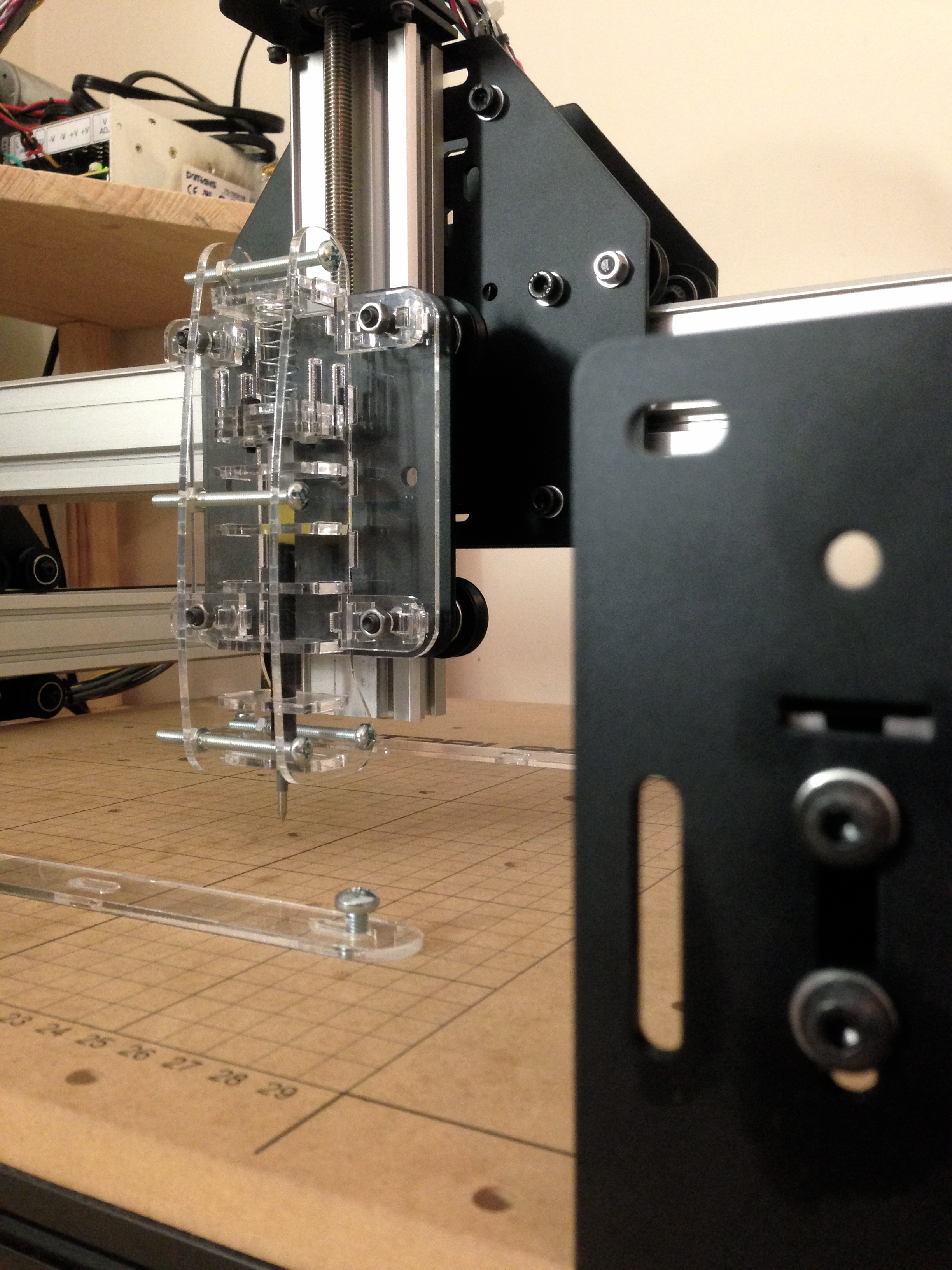
I think the look of the clear acrylic assembly compliments the matte black and aluminum Shapeoko design quite nicely. Thanks for reading and stay tuned for a few more Machine Writing DETAIL posts!
GH
